|
CFD & FEA: Introduction | CFD (details) | FEA (details)
Flow Simulation Services: CFD – Hydrodynamic Engineering. Some projects, such as, the removal of cavitation generated by a ship rudder include the use of both inviscid and viscous CFD codes.
Inviscid flow projects include:
- Propeller modelling
- Rudder modelling
- Cavitation modelling
Viscous flow projects include:
- Rudder and propeller interaction with or without the ship afterbody
- Smoke and ventilation studies
- Ship response in adverse sea conditions
- Explicit modelling of cavitation
- Wake field calculation for inviscid flow projects
- Pressure field calculation to provide boundary conditions for FEA
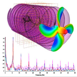
Inviscid Flow Modelling on a Propeller: BEM represents a straight forward and rapid method for determining the characteristics of a propeller.
- Transient analysis
- Rotational symmetry in the model
- From the time domain to the frequency domain
Steady State Rudder Modelling using RANS: This is a straight forward analysis with the propeller modelled by an actuator disk. From the calculation we obtain:
- The drag, lift and torque on the rudder
- The pressure field for export to FEA as a boundary condition
- An understanding of the flow field around the rudder
- A clear warning about the risk of cavitation generated by the rudder
- The wake field for use in the BEM code
Cavitation Modelling on Rudders and Propellers: Cavitation modelling for rudders involves making subtle design changes to remove the risk of cavitation. The aim is to design a rudder that does not generate cavitation. At ibmv we run the BEM code in:
- Steady state mode
- Wake field taken from the RANS code
- Calculate σy
- Co-ordinate adjustments made either automatically or interactively to the rudder to ensure σy>0.
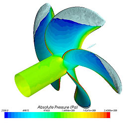
Explicit Modelling of Propeller Cavitation: Transient RANS calculation to accurately capture propeller hub and blade cavitation. The example shown includes periodic hub cavitation and the variation of cavitation wth depth. The geometry is a tanker propeller.
|